MIB 3D Volume Rendering
Overview
Starting from MIB version 2.84, a new 3D volume rendering engine is available. The 3D viewer in MIB is capable to show volumes using volume rendering techniques, models as overlays and generate surfaces from the overlay models.
Downsampling of datasets
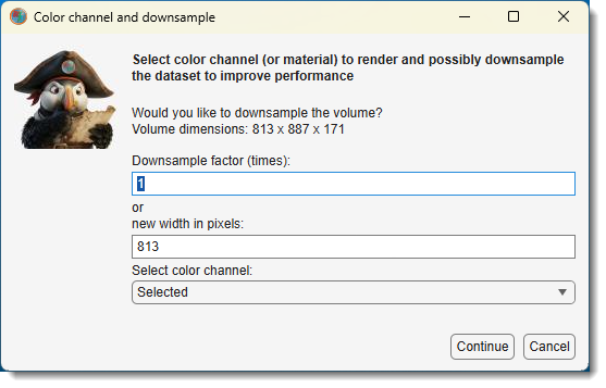
Whenever 3D volume rendering is selected, the current image volume is transferred into the 3D viewer. During the transfer, it is possible to select color channels or downsample the dataset to improve rendering performance:
Composition of the 3D viewer
The 3D viewer has two main windows:
- 3D Controls: the main window for setting parameters, generating surfaces, and making snapshots and animations. Most controls are grouped under corresponding tabs.
- 3D Viewer: the visualization window used to render volumes and models.
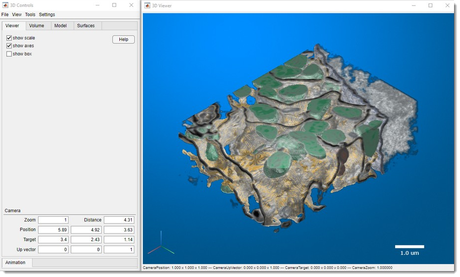
User interface of the 3D viewer
3D Controls -> Menu
Menu gives access to the following operations:
| Section | Operation | Description |
|---|---|---|
| File section | ||
| Load animation path | animations created using the 3D viewer can be saved and loaded back using this operation. | |
| Save animation path | save the current animation path to the disk. | |
| Make snapshot | starts the MIB snapshot tool to create an image snapshot of the current view. | |
| Make spin movie | starts the MIB movie maker tool to create a movie of a camera spin around the object. | |
| Make animation movie | starts the MIB movie maker tool to create an animation movie along a predefined path set in the Animation tab. | |
| View section | ||
| Default view | reset the view to its default state (also via in the upper-right corner of the 3D Viewer). | |
| XY view | set the view from above (also via in the axes, lower-left corner). | |
| XZ view | set the view from the Y-side (also via in the axes, lower-left corner). | |
| YZ view | set the view from the X-side (also via in the axes, lower-left corner). | |
| Settings section | ||
| Background color | set the background color for the scene. | |
| Background gradient color | set the secondary background color for a gradient. | |
| Background gradient | enable to render background as a gradient of two colors. |
3D Controls -> Viewer
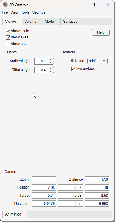
The Viewer tab allows control over the following widgets and parameters:
- : show or hide the scale bar in the 3D viewer window.
- : show or hide 3D axes; clicking the axes changes orientation.
- : show or hide the bounding box around the volume.
- : open this help section of MIB.
- : define strength of the ambient light in the scene.
- : define strength of the diffuse light in the scene.
- : define rotation center:
- rotate the scene around the current position of the mouse cursor.
- rotate the scene around the central point of the dataset.
- : when enabled, the model overlay in the 3D viewer is refreshed automatically as you segment in the main MIB window, so edits appear in 3D without pressing . Updates are debounced and triggered by data changes only (drawing, add/subtract to model, etc.) — not by panning, zooming, or slice navigation — and work for the model, mask, and selection overlays. For BigData datasets the overlay is re-fetched at the currently rendered pyramid level.
Camera
Use these widgets to specify camera position (updated interactively), it is possible to update any of these fields to modify position of the camera.
- camera zoom level.
- distance from camera to the scene center.
- camera position as a 3-element vector [x y z]. See Camera Graphics Terminology.
- camera target as a 3-element vector [x y z].
- upwards direction as a 3-element vector [x y z] (default: [0 0 1]).
3D Controls -> Volume
The Volume tab contains tools for interacting with the shown volume.
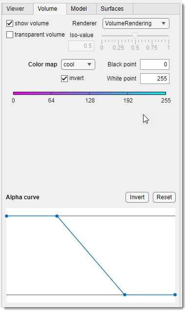
List of widgets for tweaking visualization settings:
- : toggle visibility of both volume and model (does not affect surfaces).
- : toggle volume visualization (does not affect models or surfaces).
- :
- VolumeRendering: render using color and transparency per voxel.
- GradientOpacity: render with additional transparency based on intensity/luminance gradients; adjust with the Opacity slider.
- SlicePlanes: use orthogonal slice planes, adjustable via Slices sliders or mouse.
- Isosurface: show an isosurface at the iso-value slider value.
- MaximumIntensityProjection: render the highest intensity voxel per ray (luminance for RGB).
- MinimumIntensityProjection: render the lowest intensity voxel per ray (luminance for RGB).
- / : slider to tweak GradientOpacity and Isosurface settings.
- : update the colormap; use , , and for adjustments.
- [only for SlicePlanes]: sliders to change orthogonal slice positions.
- Alpha curve: define transparency for the volume (1 = opaque, 0 = transparent).
: select the point. : change position of the selected point. - Shift +
: add a point at the clicked position. - Ctrl +
: remove the closest point. - : invert the alpha curve.
- : reset to default state.
3D Controls -> Model
The Model tab contains tools for visualizing the model loaded into MIB.
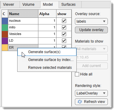
List of widgets for tweaking visualization settings:
- : specify the layer type for visualization as a model.
- : grab the layer specified in and visualize it in the 3D Viewer.
- , and : choose which materials to render, see Models with many materials below.
- : toggle show/hide all selected materials in the table.
- : pull the latest segmentation into the overlay on demand. The first use initialises the overlay (same as ); afterwards it performs a lightweight refresh that updates only the overlay data while preserving per-material visibility and display settings. This is also the action invoked automatically by .
- Table with materials: list of model materials; each can be shown/hidden and assigned a transparency value (Alpha, 0-1). Right-click for a menu with:
- Generate surface(s): create surfaces for the selected rows in the Surfaces tab. In the All materials mode the single row covers the whole model, so this builds one surface per object; it asks first, because that is one surface per object rather than one per row.
- Generate surface by index...: create a surface for any material by typing its index. For an imported overlay this reads the object ids from the store, so it works even when the objects are shown fused together.
- Remove selected materials: drop the selected rows from the rendered list (Selected materials mode only).
Models with many materials
Instance segmentation produces models with thousands of materials (the 65535 and 4294967295 model types). The 3D viewer shows up to 255 materials at a time, so these models offer two modes in the dropdown:
- All materials: everything is shown at once, using a repeating set of colors. Neighbouring objects always get different colors, so the segmentation is easy to judge as a whole. The material table has a single row that sets transparency and visibility for the whole overlay.
- Selected materials: only the materials you list are shown, each in the same color as in the 2D view and with its own transparency and show/hide switch. Type indices and ranges into the edit field, for example
1:10,45, or press to add the material selected in the main MIB window.
Tip
Use for these models. Showing the model as the volume itself gives a gradient rather than separate objects.
An imported overlay shows its objects fused into one material. Generate surface(s) on such a model builds a single surface covering all of them, after asking; objects that touch end up as one connected surface. Use Generate surface by index... for one object on its own.
3D Controls -> Surfaces
Surfaces generated from the Model tab’s material table (via right-click) are visualized using settings in this tab.
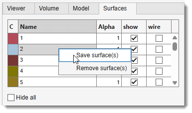
List of widgets for tweaking visualization settings:
Table:
- C: click to set color for the selected surface.
- Name: double-click to change the surface name.
- Alpha: tweak transparency (0-1).
- : toggle show/hide the selected surface.
- : toggle wireframe visualization.
- :
- Save surface(s): export selected surface(s) to SLT format.
- Remove surface(s): remove the selected surface from the 3D viewer.
: toggle show/hide all surfaces from the view
3D Controls -> Animation
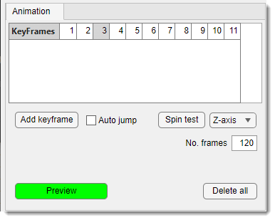
The Animation tab allows setting key frames for making movies with volume animations.
Rendering is done via
Ribbon → Home → Make animation movie
Animations can be saved/loaded from
Ribbon → Home → Load/Save animation path.
List of widgets for designing animations:
- Keyframes table: animations are based on key frames added with . Right-click for additional operations:
- Jump to the keyframe: update the viewer to the selected keyframe.
- Insert a keyframe: insert the current scene into the sequence.
- Replace keyframe: replace the selected keyframe with the current view.
- Remove keyframe: remove the selected keyframe.
- : add a keyframe to the sequence.
- : automatically update the scene to match a clicked keyframe.
- : test spinning around the specified axis ().
- : define number of frames for the preview.
- : delete all keyframes.
- : preview the animation.
Back to MIB | User interface | Ribbon | Home